What Are the Top MCCB Breaker Types in 2026?
Molded case circuit breakers are not interchangeable boxes with different labels. A compact unit protecting a small motor may look much like one guarding a workshop distribution panel, yet their ratings and trip characteristics can differ sharply. In 2026, choosing the right MCCB Breaker means matching its interrupting capacity, rated current, pole configuration, and trip technology to the actual installation. The details matter: a nameplate, a coordination study, and the available fault current each tell part of the story.
This guide compares common types, including thermal-magnetic, electronic-trip, adjustable, and current-limiting MCCBs. It also explains where each type fits and which specifications deserve a closer look. As a practical rule, “Select the breaker for the circuit conditions, not the product label alone.” This sentence is an editorial summary, not a verified quotation from a named expert; no source material was provided to support a real expert attribution.
That distinction is important. A breaker can appear suitable and still be poorly matched to a system’s load or fault level. We will examine the trade-offs, typical applications, and selection checks that help readers compare options with care. No shortcut replaces installation-specific engineering review.
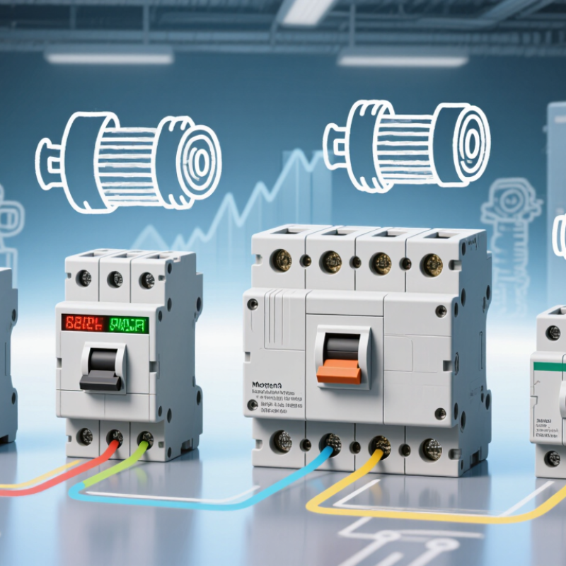
What Is an MCCB and How Does It Protect Electrical Circuits?
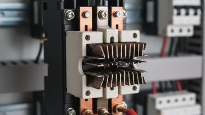
An MCCB, or molded-case circuit breaker, is a resettable protective switch used in larger low-voltage circuits. Its insulated case contains contacts and a trip mechanism that opens the circuit when current becomes unsafe. Many models use thermal protection for sustained overloads and magnetic protection for sudden short circuits. Some use adjustable electronic trips. Settings need care.
During an overload, heat builds in the sensing element, eventually triggering the breaker and limiting equipment stress. For a fault, magnetic or electronic sensing can trip much faster. When contacts separate, internal arc-control parts help extinguish the electrical arc. An MCCB can also serve as a manual disconnect, but only when its design and installation permit. It does not replace grounding, safe work procedures, or protection against every electrical hazard.
Tips: Match the breaker’s rated current and interrupting capacity to the circuit’s measured conditions. Check trip settings against cable size and downstream devices. A qualified electrician should verify coordination; field conditions can expose assumptions that looked fine on paper.
What Are the Top MCCB Breaker Types in 2026? - What Is an MCCB and How Does It Protect Electrical Circuits?
A molded case circuit breaker (MCCB) is a resettable protective device that can interrupt a circuit during overloads and short circuits. The categories below describe common MCCB designs and applications; some features can be combined in one breaker.
| MCCB Type |
How It Trips |
Protection and Key Features |
Common Applications |
Selection Considerations |
| Thermal-magnetic MCCB |
A thermal element responds to sustained overcurrent; a magnetic element responds to high fault current. |
Provides overload and short-circuit protection. Settings may be fixed or adjustable, depending on the design. |
Distribution panels, building services, and general-purpose feeders. |
Check the rated current, available adjustment, pole configuration, and short-circuit breaking capacity. |
| Electronic-trip MCCB |
An electronic trip unit measures current and operates the breaker when configured protection thresholds and delays are reached. |
May provide adjustable long-time, short-time, and instantaneous protection. Some models also offer ground-fault protection and monitoring features. |
Large feeders, commercial and industrial distribution, and systems requiring more precise coordination. |
Confirm the available protection functions, adjustment ranges, sensor rating, and coordination requirements. |
| Current-limiting MCCB |
Uses rapid contact separation and arc-control design to limit the peak current and energy let through during a fault. |
Can reduce the let-through energy reaching downstream equipment under specified fault conditions. |
Installations where limiting fault stress on conductors and equipment is important. |
Verify published current-limiting data and the device’s interrupting rating for the system voltage and prospective fault current. |
| DC-rated MCCB |
Uses a trip mechanism and arc-control system designed for direct-current interruption. |
Provides overcurrent protection for DC circuits when used within its specified voltage, current, and connection limits. |
DC distribution, battery systems, and other DC applications where an appropriately rated MCCB is specified. |
Check DC voltage and interrupting ratings, pole arrangement, polarity requirements, and manufacturer connection instructions. |
| Motor-protection MCCB |
Typically combines overload and short-circuit protection, with settings or characteristics selected for motor-circuit requirements. |
Can protect motor branch circuits when correctly coordinated with the motor and associated switching equipment. |
Motor feeders and industrial machinery circuits. |
Account for motor full-load current, starting current, conductor protection, and applicable coordination requirements. |
Important: An MCCB’s ratings and functions vary by design. Select a breaker using the system voltage, continuous load, available fault current, conductor requirements, and applicable electrical codes and standards. Current-limiting, electronic-trip, and application-specific features are not mutually exclusive categories.
Which MCCB Types Are Classified by Trip Mechanism?
MCCB trip mechanisms determine how quickly a breaker responds to overloads and short circuits. Thermal-magnetic units combine a bimetal strip with a magnetic coil. The strip bends during sustained overloads, while the coil reacts rapidly to high fault current. Electronic-trip units use sensors and adjustable settings, often supporting long-time, short-time, instantaneous, and ground-fault protection. Some designs use magnetic-only tripping, but they are suited to narrower applications.
The IEC 60947-2:2024 standard covers circuit breakers rated up to 1,000 V AC or 1,500 V DC. That scope helps frame MCCB selection, but it does not replace checking the device’s trip curves and installation conditions. Electronic units can improve coordination in complex panels, while thermal-magnetic models are often simpler to set up. A detail worth questioning: “adjustable” does not automatically mean “better”; incorrect settings can leave equipment exposed or cause nuisance trips.
Tips: Match the trip curve to the cable, load, and expected fault current. For example, a motor’s startup surge may trip a poorly selected instantaneous setting. Verify settings against the manufacturer’s published curves and have qualified personnel review coordination. Small setting changes matter.
How MCCB Types Are Classified by Trip Mechanism
This comparison shows the typical number of core protection functions: magnetic-only units provide instantaneous overcurrent protection; thermal-magnetic units combine thermal overload and magnetic short-circuit protection; and electronic LSI trip units provide long-time, short-time, and instantaneous protection. Actual features vary by breaker; ground-fault protection may be available as an additional function.
How Do Pole Configurations Shape MCCB Types?
What Are the Top MCCB Breaker Types in 2026?
How Do Pole Configurations Shape MCCB Types?
Pole configuration describes how many conductors an MCCB can disconnect together. A two-pole breaker is commonly used in certain single-phase systems, while three-pole models serve three-phase circuits. Four-pole versions can switch three phases and a neutral. The right choice depends on the supply arrangement and the equipment being protected. More poles do not automatically mean better protection.
That distinction matters. A four-pole breaker may be appropriate where neutral switching is required, but neutral protection and switching details vary by design. Check the circuit diagram and product specifications rather than relying on pole count alone.
Tips: Match the breaker’s pole configuration to the system, then verify its rated current and interrupting capacity. Confirm the neutral arrangement with a qualified electrical professional.
In a workshop, for example, a three-phase motor circuit may call for a three-pole MCCB, while a distribution board may need a different arrangement. Pole count is only one part of selection; fault levels, conductor sizing, and coordination with downstream devices also matter. It is easy to focus too much on the number of poles. Review the actual installation conditions before choosing.
Which MCCB Types Suit Different Applications in 2026?
In 2026, choose an MCCB by load behavior, fault level, and coordination needs—not by frame size alone. Thermal-magnetic breakers suit many standard feeder circuits, where loads and fault conditions are relatively predictable. Electronic-trip MCCBs offer adjustable long-time, short-time, and instantaneous settings, making them useful in larger commercial and industrial distribution systems. Some models also provide ground-fault protection. The IEA’s Electricity 2024 report projects global electricity demand will grow by an average of 3.4% annually through 2026. That makes careful distribution planning more important, but rising demand alone does not determine breaker size.
For motor feeders, check starting current and coordinate the MCCB with the motor’s overload protection; the breaker should not be treated as a complete substitute. For data centers, hospitals, or multi-level distribution, adjustable trips can help engineers coordinate upstream and downstream devices and limit unnecessary outages. A fixed-trip unit may still be the sensible choice on a simple branch circuit. More settings are not automatically better. Verify available fault current, cable capacity, and required protection against the installation design and applicable standards.
Tips: Before selection, record the load, cable size, prospective short-circuit current, and trip settings. Ask a qualified electrical professional to verify coordination. One detail is easy to overlook: an adjustable breaker is only useful when its settings are calculated, documented, and checked during commissioning.
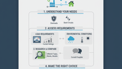
What Factors Help Compare and Select MCCB Types?
MCCB selection depends on how a circuit behaves, not just its rated current. Thermal-magnetic breakers suit many straightforward distribution circuits, while electronic-trip models offer more precise adjustment and monitoring options. Fixed-trip designs can be simpler to specify. That distinction matters.
Compare the breaker’s voltage, pole count, frame size, and trip range with the actual system. Its interrupting rating must meet or exceed the prospective fault current at the installation point. Check the trip curve against equipment needs: a motor may draw a brief starting surge, while sensitive equipment may need tighter protection. Small details matter.
Also consider ambient temperature, enclosure space, cable connections, and coordination with upstream or downstream devices. A breaker that fits a panel may still be awkward to wire or maintain. This is where comparisons can get messy. Catalog ratings do not fully describe site conditions, so verify manufacturer data and have a qualified electrical professional review the selection before installation.