| Protection Technology |
Use a thermal-magnetic MCCB when both overload and short-circuit protection are required without electronic communication functions. |
Thermal trip for sustained overloads; magnetic trip for high-current faults. |
Confirm that the breaker is suitable for the circuit voltage, frequency, conductor system, and enclosure arrangement. |
Check trip mechanism movement during scheduled inspections and investigate nuisance tripping before resetting repeatedly. |
Suitable for general distribution, motor feeder, lighting, and commercial or industrial feeder applications. |
| Rated Operational Voltage (Ue) |
Select a voltage rating equal to or higher than the system voltage. |
Common low-voltage applications include 230/400 V AC and 480 V AC systems; some MCCBs are rated up to 690 V AC. |
Verify phase-to-phase and phase-to-neutral voltages, system earthing arrangement, and applicable local code requirements. |
Inspect terminals and insulation for heat discoloration, cracking, contamination, or signs of tracking. |
A higher voltage rating alone does not compensate for inadequate interrupting capacity or incorrect system configuration. |
| Rated Current (In) |
Choose a frame and trip rating that protect the conductors while supporting the expected continuous load. |
Common MCCB trip ratings range from approximately 15 A to 1,600 A; larger ratings are available for specialized equipment. |
Apply the continuous-load rule required by the governing electrical code and account for ambient-temperature derating. |
Check for overheating at line and load terminals using torque verification and, where permitted, infrared inspection. |
The trip rating should not exceed the allowable ampacity of the protected conductor unless a code-specific exception applies. |
| Frame Size |
Use the smallest suitable frame size that meets the required current, interrupting, accessory, and coordination needs. |
Typical frame groups include 100 A, 250 A, 400 A, 600 A, 800 A, and 1,600 A classes. |
Reserve adequate space for cable bending, heat dissipation, terminals, barriers, and future accessories. |
Verify that mounting hardware, terminal kits, and internal accessories remain secure and undamaged. |
Frame size affects physical dimensions, terminal capacity, accessory compatibility, and available adjustment range. |
| Short-Circuit Interrupting Capacity |
Select an interrupting rating equal to or greater than the prospective fault current at the installation point. |
Common ratings include 10 kA, 18 kA, 25 kA, 35 kA, 50 kA, and 65 kA at the specified voltage. |
Obtain the available fault current from a qualified short-circuit study or utility and system calculation. |
After a high-fault event, inspect or replace the MCCB according to the applicable product instructions and safety rules. |
Interrupting capacity must be evaluated at the actual voltage and system configuration, not only by the maximum catalog value. |
| Magnetic Trip Setting |
Set the instantaneous magnetic pickup high enough to avoid unwanted operation during normal inrush, but low enough to clear severe faults promptly. |
Many adjustable magnetic settings are approximately 5 to 10 times the rated current, depending on the MCCB design. |
Consider transformer energization, motor starting current, capacitor inrush, and downstream selectivity. |
Record the setting and verify it against the approved coordination study after maintenance or system modification. |
Correct adjustment improves fault clearing while reducing nuisance trips during equipment startup. |
| Thermal Trip Function |
Use the thermal element to protect against prolonged overloads and conductor overheating. |
Thermal response is time-dependent and influenced by current, ambient temperature, and prior loading. |
Do not install the MCCB in an enclosure or ambient environment that exceeds its rated operating conditions. |
Check for repeated overload events, blocked ventilation, loose connections, and abnormal operating temperature. |
Thermal protection is important for cable protection but should be coordinated with downstream protective devices. |
| Poles and Switching |
Match the number of poles to the circuit arrangement and local requirements for neutral switching and isolation. |
Two-pole, three-pole, and four-pole configurations are commonly used in low-voltage systems. |
For a four-wire system, determine whether the neutral must be switched and whether the neutral pole requires overcurrent protection. |
Operate each pole through its normal mechanical mechanism and confirm that contacts open and close together as intended. |
Incorrect pole selection can compromise isolation, maintenance safety, and system fault protection. |
| Installation Orientation |
Install the MCCB in the orientation and position permitted by its technical documentation. |
Many devices support vertical mounting, while allowable horizontal or reverse-feed installation may vary. |
Maintain required clearances, creepage distances, ventilation paths, and access for operation and testing. |
Inspect for loosened mounting screws, enclosure vibration, dust accumulation, and restricted airflow. |
Incorrect orientation can affect heat dissipation, terminal safety, mechanical operation, or certification conditions. |
| Terminal Connections |
Use conductors, lugs, torque values, and termination methods specified for the selected MCCB. |
Terminal sizes commonly accommodate copper or aluminum conductors within a defined cross-sectional-area range. |
Strip conductors correctly, prevent insulation under the clamp, and avoid excessive bending force on terminals. |
De-energize and apply the required safety procedure before torque checks; never retorque energized equipment. |
Loose or incorrectly sized terminations are a major cause of heating, arcing, and premature failure. |
| Conductor Compatibility |
Coordinate conductor material, cross-sectional area, insulation temperature rating, and ampacity with the MCCB terminals. |
Typical low-voltage feeder conductors use copper or aluminum with insulation ratings commonly between 75°C and 90°C, subject to code limits. |
Confirm terminal suitability for the conductor material and use approved joint compounds where required. |
Look for oxidation, strand damage, discoloration, and deformation at the termination point. |
Conductor compatibility affects connection reliability, temperature rise, and long-term protection performance. |
| Selectivity and Coordination |
Coordinate upstream and downstream protective devices so the device nearest the fault operates first where practical. |
Coordination may be evaluated using time-current curves, instantaneous settings, and manufacturer-tested combinations. |
Complete a protection coordination study for important feeders, generators, transformers, and large motor systems. |
Review settings after changes to transformer impedance, generator capacity, feeder length, or downstream equipment. |
Proper coordination improves service continuity and limits unnecessary shutdowns during faults. |
| Motor Feeder Application |
Account for motor starting current, locked-rotor current, overload protection, and short-circuit protection separately. |
Motor starting current may be several times the full-load current, depending on motor type and starting method. |
Set the magnetic pickup to tolerate normal starting while maintaining code-compliant motor-circuit protection. |
Investigate trips during startup, excessive starts per hour, mechanical overload, and voltage imbalance. |
An MCCB may provide short-circuit protection but does not replace a properly selected motor overload device. |
| Ambient Temperature |
Apply the manufacturer’s current adjustment data when the ambient temperature differs from the reference condition. |
Reference ambient conditions are often based on approximately 40°C, but the exact value depends on the device standard and design. |
Account for enclosure heat, nearby equipment, solar gain, altitude, and grouped devices. |
Trend operating temperature and investigate sustained temperatures above the design condition. |
Thermal-magnetic trip behavior changes with temperature; derating may be necessary for reliable operation. |
| Altitude and Environment |
Check altitude and environmental limits for installations above standard low-voltage test conditions. |
Above approximately 2,000 m elevation, insulation performance, cooling, and current capability may require evaluation. |
Consider humidity, salt mist, corrosive gases, dust, vibration, and outdoor enclosure protection. |
Clean using approved methods and inspect seals, ventilation filters, corrosion, and condensation control. |
Environmental derating and enclosure selection are essential for reliable service in demanding locations. |
| Ingress Protection |
Select the enclosure and installation arrangement according to the required IP or equivalent environmental protection level. |
IP ratings are defined by IEC 60529; the first digit addresses solid-object protection and the second addresses water protection. |
Use appropriate gland plates, conduit entries, seals, and drainage provisions without compromising the enclosure rating. |
Inspect door seals, cable entries, covers, and drainage points during routine maintenance. |
The MCCB’s internal rating does not automatically define the environmental protection of the complete assembly. |
| Standards and Compliance |
Use equipment tested and documented for the target market and installation category. |
IEC 60947-2 is widely used for circuit-breakers; regional installation codes and certification requirements may also apply. |
Confirm documentation for rated voltage, current, interrupting capacity, temperature, altitude, and accessory combinations. |
Keep certificates, wiring diagrams, test records, settings, and inspection history with the equipment documentation. |
Compliance must cover the complete installation, including the enclosure, busbar system, conductors, and protective coordination. |
| Routine Inspection |
Establish an inspection interval based on duty, fault exposure, environment, criticality, and local regulations. |
Common programs include visual inspection, mechanical operation checks, thermal inspection, and electrical testing. |
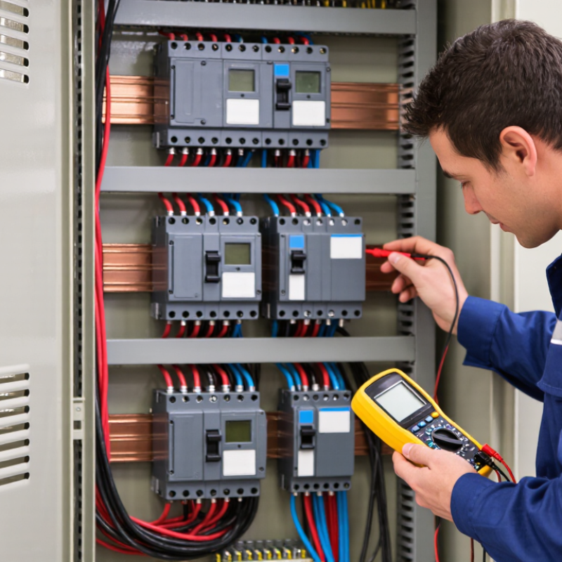
Only qualified personnel should access live or potentially energized equipment, using the required lockout and verification procedures. |
Record trip settings, torque checks, test results, abnormal conditions, and corrective actions. |
A documented preventive-maintenance program reduces unexpected downtime and identifies deteriorating connections early. |
| Insulation Testing |
Perform insulation-resistance or dielectric tests only when appropriate for the device and the complete circuit. |
Test voltage and acceptance limits depend on the applicable standard, equipment design, and manufacturer instructions. |
Disconnect or protect electronic accessories and sensitive components before applying test voltage. |
Compare results with previous records and investigate significant deterioration rather than relying on a single reading. |
Testing supports insulation condition assessment but does not replace visual inspection or functional verification. |
| Lifecycle Replacement |
Replace the MCCB when it shows severe contact wear, failed trip operation, insulation damage, or unverified fault exposure. |
Service life depends on electrical and mechanical operating cycles, load type, fault duty, temperature, and environment. |
Maintain an equivalent or improved interrupting rating and confirm compatibility with existing terminals and accessories. |
After replacement, verify torque, phase identification, trip settings, operation, and documentation. |
Replacement decisions should be based on condition and duty history rather than age alone. |