Leave Your Message
-
Phone
-
E-mail
-
Whatsapp
-
Whatsapp

Choosing the right Ac Contactor Arc Chute is not a minor component decision. It directly affects switching reliability, contact life, heat control, and operator safety. When an AC contactor opens, the contacts separate under electrical load. An intense arc can form between them. The arc chute must stretch, cool, split, and extinguish that arc within a very short time.
Electrical engineer Dr. Martin Keller explains, “A contactor does not merely interrupt current; it must control the energy released by that interruption.” This principle should guide every selection. A suitable Ac Contactor Arc Chute must match the contactor’s rated voltage, operating current, frequency, utilization category, and short-circuit environment. It should also fit the original chamber accurately. A small dimensional error can create weak insulation, poor airflow, or unwanted flashover.
Look closely at the material. Heat-resistant insulating polymers, ceramic barriers, and metal splitter plates serve different operating demands. In dusty panels, surface tracking deserves attention. In high-frequency switching, thermal stress may become the hidden problem. Do not judge performance by appearance alone.
Field experience also reveals an uncomfortable truth: the “universal” arc chute is often only nearly compatible. That may be enough for a test bench, but not for continuous industrial duty. Verify manufacturer data, installation clearances, replacement history, and actual load conditions. If the available documentation is incomplete, stop and investigate. A confident guess is still a guess.
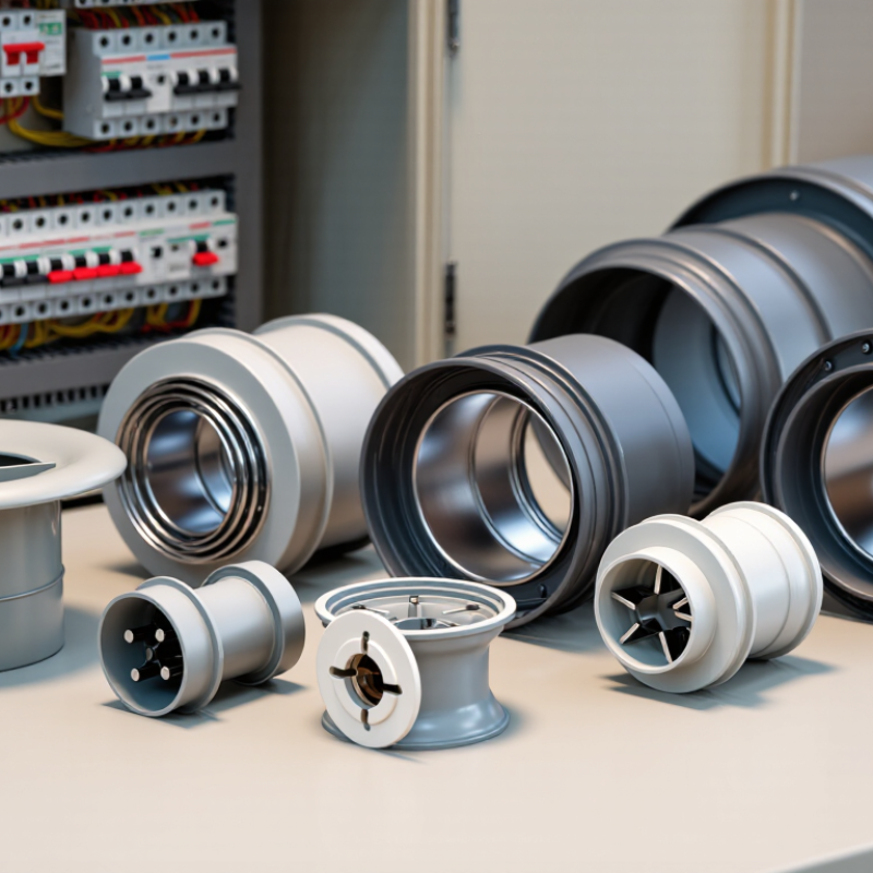
How to Choose the Right AC Contactor Arc Chute?
Understanding the Role of an AC Contactor Arc Chute
An AC contactor arc chute controls the electrical arc created when contacts separate. Without it, the arc can stretch across the contact gap, causing heat, noise, and contact damage. Inside the chute, metal plates divide the arc into smaller sections. These plates cool, lengthen, and deionize the arc until it stops. This protects nearby insulation and helps the contactor interrupt current more safely.
Selecting the correct chute requires more than matching physical size. Check the contactor’s rated voltage, operational current, AC frequency, and switching duty. A motor circuit may produce stronger arcing than a simple resistive load. Short-circuit conditions also matter. The chute must fit securely, maintain the required insulation distance, and tolerate the panel’s temperature and dust levels. A 10 mm dimensional mismatch can prevent proper assembly.
During maintenance, inspect for cracked plates, carbon deposits, loose mounting points, or heat discoloration. Small damage can reduce arc control before failure becomes obvious. I would not select a replacement by appearance alone. That approach is quick, but unreliable. Manufacturer data and applicable electrical standards should guide the decision. Even experienced technicians can overlook airflow, enclosure temperature, or frequent inching operations. The choice may need a second review.
| Selection Dimension | What to Check | Typical Engineering Reference | Why It Matters | Verification Method |
|---|---|---|---|---|
| Rated operational voltage | Confirm the arc chute is designed for the contactor’s AC system voltage and insulation requirements. | Common low-voltage AC systems include 230 V, 400 V, 480 V, and 690 V. The arc chute rating should not be lower than the contactor’s rated operational voltage. | Higher voltage produces a more persistent arc and requires adequate arc separation and insulation distance. | Compare the contactor nameplate, technical datasheet, and applicable product standard. |
| Continuous current and utilization category | Match the arc chute to the contactor’s current rating and load duty, rather than selecting by motor current alone. | AC-1 is generally associated with mainly resistive loads; AC-3 is commonly used for squirrel-cage motor starting and switching during normal operation. AC-4 involves inching, plugging, or frequent reversing and creates more severe arcing. | The same current can generate very different contact erosion and arc energy under different utilization categories. | Identify the load type, starting method, switching frequency, and utilization category in accordance with IEC 60947-4-1 or the applicable local standard. |
| Pole configuration | Check the number of poles, pole spacing, mounting orientation, and whether the chute is intended for a specific contact system. | Three-pole arrangements are common for three-phase motor circuits; four-pole arrangements are used where the neutral must also be switched. | Incorrect pole spacing or alignment can reduce arc control and may prevent reliable mechanical operation. | Measure the contactor’s pole pitch, mounting points, and moving-contact travel against the chute drawing. |
| Arc-quenching construction | Look for a suitable arc chamber, splitter plates, insulating barriers, vent paths, and adequate arc-running surfaces. | Metal splitter plates divide the arc into shorter arcs and help cool and de-ionize it. Insulating barriers help prevent flashover between poles. | Effective arc control reduces contact wear, limits heat damage, and supports faster interruption of the current. | Inspect the internal plate arrangement, plate condition, vent openings, and clearances for damage or obstruction. |
| Insulation and dielectric withstand | Verify insulation coordination, creepage distance, clearance, and dielectric withstand capability. | The required values depend on rated insulation voltage, overvoltage environment, pollution degree, altitude, and enclosure design. | Adequate insulation reduces the risk of pole-to-pole or pole-to-ground flashover after switching. | Use the manufacturer’s test data and the insulation-coordination requirements of IEC 60947-1 or the relevant standard. |
| Material temperature capability | Check the thermal stability, flame behavior, and resistance to arc by-products of the insulating housing and plates. | Thermoset or high-temperature engineering insulating materials are commonly used where repeated arcing and elevated chamber temperatures occur. | Materials that soften, crack, carbonize, or deform can reduce insulation distance and cause repeated faults. | Review material specifications, flammability information, and evidence from thermal endurance or type testing. |
| Switching frequency and electrical endurance | Estimate the number of operations per hour and the required electrical life under the actual load. | Frequent cycling, jogging, reversing, and inching generally require a more robust arc chute than occasional motor starting. | Higher operation counts increase arc exposure, contact erosion, heat accumulation, and maintenance demand. | Calculate expected operations over the service life and compare them with the tested electrical endurance at the intended utilization category. |
| Short-circuit coordination | Ensure the contactor and arc chute are coordinated with the upstream fuse or circuit breaker. | Coordination is assessed using the prospective short-circuit current and the specified type of coordination. The arc chute is not a substitute for short-circuit protection. | A suitable protective device limits fault energy and helps prevent severe damage to the contactor assembly. | Compare the installation fault level with the tested coordination tables for the complete starter or switching assembly. |
| Environmental conditions | Assess ambient temperature, humidity, dust, corrosive gases, vibration, altitude, and enclosure ventilation. | Pollution degree, altitude, and temperature can require derating or increased clearance. Dust and conductive contamination can obstruct vents and create tracking paths. | Environmental stress can reduce insulation performance and accelerate thermal or mechanical degradation. | Compare site conditions with the permitted operating range and apply the installation standard’s derating guidance. |
| Mechanical fit and contact travel | Confirm dimensions, retaining features, moving-contact clearance, arc-horn position, and ease of removal for maintenance. | The arc chute must remain securely positioned throughout the contactor’s full opening and closing movement without restricting travel. | A loose, misaligned, or obstructed chute can cause uneven contact wear, overheating, or failure to interrupt the arc correctly. | Perform a dimensional check and a manual operating test with the circuit isolated and de-energized. |
| Inspection and replacement condition | Check for cracked insulation, burned or missing splitter plates, carbon deposits, blocked vents, and excessive erosion. | Replacement is advisable when damage changes clearances, restricts venting, weakens mounting, or leaves visible evidence of severe arcing. | A visibly damaged arc chute may no longer provide the designed interruption and insulation performance. | Use a documented maintenance interval and compare the component with its original inspection criteria or service limits. |
| Compliance and test evidence | Select a component supported by test documentation for the complete contactor assembly, not only by a dimensional match. | IEC 60947-1 covers general low-voltage switchgear requirements, while IEC 60947-4-1 addresses contactors and motor starters. Other markets may use corresponding regional standards. | Arc performance depends on the complete contact system, chamber geometry, and protective-device coordination. | Request type-test reports, ratings, installation instructions, and traceable technical documentation. |
Selection note: Arc-chute ratings and dimensions are not universal. Always verify the complete contactor assembly, load category, operating voltage, short-circuit coordination, installation environment, and applicable local requirements before replacement or design approval.